Flux Health Forum

DIY Coils for PEMF

when you say “device”, do you mean a battery pack?

No need to answer that because that specific clarification will not change the answer:

There is no way to know. Every product is different, and they change from batch-to-batch (consider LED light bulbs, where detailed EMI testing reveals that the exact same type of bulbs vary wildly in their EMI emission, depending on exactly when they were manufactured). You would need to test each product in question. That costs about $23,000 last time I paid for it in 2007.

But the real problem is that they would test to federal standards, which would tell you that the device itself meets federal standards, and we all know that federal standards allow a lot of devices that emit hazardous EMI. So this is an easy question to ask but impossible question to answer unless you hire a lab that is willing to develop and run a special test.

You will notice that no one offers the service of testing individual consumer electronics for all forms of potential EMI. That’s because the cost of testing would be 10s of thousands of dollars per device, and typical consumer is not interested in spending $10,000 - $20,000 to know whether or not their toaster or cell phone is really safe, beyond federal standards.
To simplify, I just mean that virtually all the PEMF is coming from the coils and virtually none from the battery pack with the flashing light where I assume all the electronics are and the pulses are generated, correct?

I think you mean the ICES-PEMF Pulse generator, not the battery pack. It is the device you plug the coils into.

The good news is that, unlike most other products, I have tested extensively to assure that Micro-Pulse ICES-PEMF devices do not emit detectable levels of harmful EMI.

I demonstrate this in a video:

The information you want starts at time 13:20

Ok, great, NOW we’re on the same page! I just figured since I snap the battery into the A9 that the battery pack and pulse generator were one and the same and we were talking about the same thing…

Hi could you please tell me the specific details of the coils for the A9a ? I investigated and found they have 0.3mm wire 0.8-1 ohm’s and around 43 turns at 37/42 mm diameter is there any other important details for them kind regards

that’s correct.

[extra text characters added to meet the forum post minimum]

Hi Eddy, curious - you a EE?

hi, are you referring to an Electrical Engineer ? not quite, i am actually in he Biotechnology / (Clinical psychology) field of sciences

Yes, I was referring to Electrical Engineer. That is very cool! Not too many on the forum get to the level of technical question you asked. :slight_smile:

Isn’t the strongest part of the magnetic field, in terms of flux density, at the center of the coil? Like with an MRI machine, basically a giant coil they put you in the middle of then pulse up a 1.5 to 2.5T magnetic field in there.

Generally that’s true. Our coils (and all commercial clinical PEMF coils) are solenoid coils. The magnetic field is distributed accordingly:

In the case of PEMF coils, they are “short” so they do not exactly match the simplifying assumptions of a “long” solenoid coil.

1 Like

@Bob

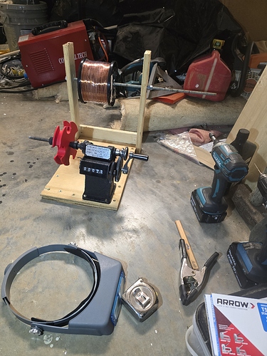
Good afternoon, I know this is an older post (DIY Coils for PEMF) but I am tinkering around with building my own DIY PEMF. And had a few questions on the topic of coils. Specifically I was curious about the coil windings; are yours wound orthocyclicly or do they use jumble winding? I’m just trying to decide if it matters with regard to the use case of PEMF. I would prefer to go with orthocyclic winding, however I’m not sure how I would retain that tight coil shape. As I’m typing this it occurs to me that I could 3D print retained forms (like a U-channel spool that slides on/off my winding spindle), and then tape it to secure it (the coil) in the form after winding. Just back of the napkin spitballing here. Again I was looking for some advice from someone who has probably pondered these questions long before me, as to whether the complication (orthocyclic vs. jumble winding) is worth the trouble, and figured there is no one better to ask. Thanks in advance for your time.

I just use a 3D printed form to hold the coils to the diameter I want, wind by hand, then bind the wires together. Nothing special or precise. To bond you can just use tape, crazy-glue, etc, but I use heat or solvent bondable coated wire. (specific wire I use: MWS company, 28 AWG Bond 1, bond after winding with 91% isopropyl alcohol.)

2 Likes

Thanks Bob, I will look into that!

… of course I design the coil winder so that it can release the coils once bonded. I just design a split spool and unbolt it when the coil is bound into shape.

Yep I have a split spool that I 3D printed.! I’m a little concerned the PVB may stick to my PLA spool though. I could wax the spool I suppose. Thanks again for the wire recommendation!

yup, thin burnished coat of canning wax works great.

1 Like

Your setup looks great, BTW. Those old-skool mechanical timers are excellent. I have a small collection of them. They are getting hard to find.

Do you use a wick to apply alcohol as you’re winding, or just a spray bottle, or what method do you use for that? Also do you heat them afterwards to ensure all solvent has off gassed?

I wind the coils. I leave radial channels in the 3D fabricated winding spool (or I use CNC machined Teflon), then when fully wound, I add a few drops of 91% alcohol into each radial channel and allow it to flow into the coil windings. Let air dry 24 hours. Demold.

2 Likes